
AWC Electronics - Servo Bot
It seems like most people who work with Basic Stamps eventually get the bug to build a robot. My robots are usually recycled toys. A little probing around any remote control toy will tell you where to connect your Stamp to make it move. As a bonus, you can cut that trace and read the remote control on some input pins as well! (That's a project I'll show you some other time).
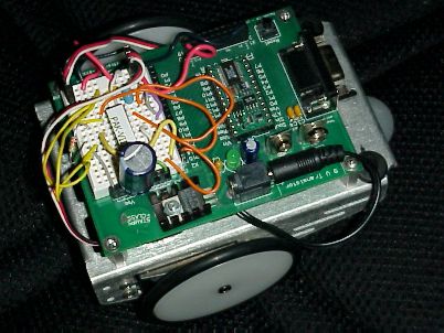
Parallax has a BOE-Bot, that is a nice beginner's robot platform. I used these last year to teach some fifth graders about robotics. If you haven't seen these, they are a small chassis that holds a "Board of Education", a battery pack, and two servos. A "drag" wheel keeps the thing from tipping over.
The Bot uses servos instead of ordinary motors. Servos have the advantage that you can drive them using the Stamp outputs directly. The disadvantage -- that we will solve this month -- is that when the Stamp is driving the servos, it can't do anything else.
Servos??
The problem with servos is that they only move in an arc, right? Robot wheels need to spin, not just move a few degrees. Parallax provides instructions with the kit that allows you to modify the servos to rotate.
The basic idea behind a servo is that it is a motor with a variable resistor coupled to the shaft. When you send the servo a pulse, it generates a pulse using the variable resistor and compares the two pulses. If the pulses are the same, the motor is in the right position. If not, the motor moves to try to make the pulses equal. So a short pulse will cause the motor to move one way and a long pulse will make it move the other way.
When you modify a servo for continuous rotation, you remove the coupling between the shaft and the pot (leaving the pot in the center position). You also remove the stops that prevent the motor from moving too far.
Most servos have a "center" position that corresponds to a 1.5mS pulse. You can wait about 20mS between position commands (although this isn't very critical). So with the modifications in place a 1.5mS pulse will hold the robot's position (if you don't send any signal, the wheels will move easily -- the center pulse will somewhat "lock" the wheels). If you send a pulse less than 1.5mS long the wheels will move a bit in one direction. The smaller the pulse, the more the wheels will move (up to some limit). Longer pulses make the wheel go in the opposite direction. Again, the longer the pulse, the further the wheel will travel with each pulse.
The Problem
I did an article for Elektor magazine awhile back that showed how to connect the BOE Bot to an IR sensor and control it with a Sony remote control. I wound up with code that would read a button from the remote and then make the motor move a predetermined amount. You could hold down the 2 button (I think it was the 2 button) and the robot would move forward, relatively slowly. The 8 button was reverse and the 4 and 6 buttons made turns.
I thought about making it where you could press 2 and make the robot move forward until you pressed another button (say 5). This made the robot very jerky. Why? Because the code I used to read the IR remote had to "time out" with no input. That left very little time for the wheels to move. When you hold down a key, the IR code would do its work quickly, but -- for reasons I won't go into here -- you had to read a long series of non-existent pulses before you could figure out that there was no input!
What you need is some way to set the motor speeds and have them "stick" while the Stamp is free to do something else. The AWC PAK-VIII coprocessor is just the ticket for this task. It can generate arbitrary pulses on 8 channels at the same time. In this case, I only need 2 channels, but you could use the other channels for some other gadgets on your robot (an arm or a dish antenna maybe?).
The PAK
The PAK is very simple to use. You send it data using SHIFTOUT and receive data using SHIFTIN. The protocol is not speed-sensitive and you don't have to wait on the PAK for results (which would, after all, defeat the purpose).
The PAK-VIII comes with a Basic Stamp library that hides all the SHIFTIN/SHIFTOUT commands from you and the code this month uses it. The code that you would write appears in red.
Each channel of the PAK has a series of registers. One register sets the "on" time for the pulse and the other sets the "off" time. You can also set an optional count to control how many pulses are generated. Without the count, the PAK continues to create pulses until you issue more commands.
You can also force the state of any channel if you like. You can read the entire PAK-VIII manual online.
The Only Problem...
About the only problem is that once you put a PAK-VIII on the tiny BOE-Bot's breadboard, you won't have room for too much other circuitry. In practice, you'll probably want to build a small board to plug into the BOE-Bot's expansion connector, or one that rises above the breadboard. The only connections required are two I/O pins, power, and ground (plus battery power if you are going to connect the servos on your board instead of the breadboard).
Another option is to remove the Board of Education and replace it with a larger breadboard. You can use an ASP-II to program the Stamp. This will let you build more substantial circuits anyway.
Because of this limitation, the example code only shows the Stamp pausing while the motors are running. However, you could do useful work during that pause. You could read an IR sensor, receive serial data from an RF receiver or do anything else you can imagine. The motors will follow their commands until you reprogram the PAK-VIII.
The Circuit
Other than space considerations, adding a PAK-VIII to the BOE-Bot is simple. Follow the directions in the Stamp VIII manual's example circuit (see above) for connecting the resonator and the enable pins. Then you can connect the data pins and clock pins to the Stamp (I used P15 and P14 for the data and clock). You need a pull up resistor (10K to 22K to 5V) on the data pins. A pull down resistor on the clock line is useful if you plan to put the Stamp to sleep or use the End statement.
Of course, the PAK-VIII needs 5V and ground connected as shown in the manual. You can connect the servo pulse inputs (usually the white wires) to the PAK's output channels (P0 and P1)..
The Code
The program below uses the PAK-VIII's channel 0 and 1 to drive the BOE-Bot's servos. The time base is at the default, 10uS. The basic sequence of events is:
1. Disable both channels
2. The ServoCenter routine sets both channels to (nominally) 1.5mS on and 20mS off. Since the servos may stop at slightly different times, the code uses center0 and center1 to set the actual center time for each servo separately.
3. Turn on both channels
4. Set both servo pulses to 2mS. This will cause the servos to rotate in the same direction. Since the servos are "back to back", the robot will spin in place.
5. Pause for 10 seconds.
6. The code sets servo #1's pulse to 1mS. This will reverse its direction and cause the robot to move forward (or backwards, depending on how you've mounted the servos).
7. Another 10 second pause.
8. ServoCenter stops the servos again.
9. The code loops. An End here will cause the Stamp outputs to become inputs momentarily every few seconds (this is an artifact of the watchdog timer on the Stamp). The PAK can become confused if this happens, although you can prevent it by using a pulldown resistor (say a 22K resistor to ground) on the clock line.
Here is an oscilloscope picture of the two channels running in the center position:
The center positions were both set to 1.5mS for this shot. The offset on the edges between the two channels is the amount of time it takes the Stamp to enable one channel and then the other.
If you bought your PAK-VIII after 1 November 2000, it has two additional commands ($FE and $FD) that you can use to shut the PAK timer down so you can set up your outputs and then start the timing up again. This would result in perfect alignment of the pulses. But it also means the entire chips stops producing output until you turn it on again. For servo applications, this slight offset is no problem.
Stamp Code
' Servo BOE-Bot demo for PAK-VIII ' Change these to suit your setup datap con 15 ' Data pin (I/O) datapin var in15 clk con 14 ' Clk pin (output) ' Register names DURLOW con %000 DURHIGH con %001 HIGHDUR con %010 LOWDUR con %011 PSCALE con %100 PSBASE con %101 N con %110 CTRL con %111 center0 con 150 center1 con 152 output clk output datap fpx var word ' Integer used by some routines fpb var byte ' byte ' parameters for FCommand chan var nib register var nibdebug "reset",cr gosub freset ' always reset! gosub FTotalReset ' hard reset top: ' disable channel 0 and 1 chan=0 register=6 fpx=1 gosub FCommand chan=1 gosub FCommand gosub ServoCenter ' turn on and enable chan 0 and 1 for chan=0 to 1 fpb=3 gosub FJam next ' Set both servos to 2mS (200) ' Since servos are "back to back" ' the robot will rotate chan=0 register=1 fpx=200 gosub FCommand chan=1 gosub FCommand pause 10000 ' rotate for 10 seconds chan=1 register=1 fpx=100 ' go in one direction (reverse servo#1) gosub FCommand pause 10000 gosub ServoCenter stopp: goto stopp end ' Center both servos ServoCenter: chan=0 register=1 fpx=center0 ' 150 x 10 = 1.5mS gosub FCommand chan=1 fpx=center1 gosub FCommand register=2 fpx=2000 ' 2000 x 10 = 20mS gosub FCommand chan=0 goto FCommand ' let FCommand return ' Reset the Pak8 I/O FReset: LOW DATAP LOW CLK HIGH CLK HIGH DATAP LOW CLK return ' 0 is 0, 1 is 1, 2 is hi-z, 3 is normal ' note: 3 enables channel to run! FJam: fpb=chan + (fpb<<3)+%01000000 goto FSendByte FCommand: ' inputs chan = channel, register = register fpb=(register<<3) + chan gosub FSendByte fpb=fpx.lowbyte gosub FSendByte fpb=fpx.highbyte goto FSendByte FReadReg: fpb=(register<<3) + chan + %10000000 gosub FSendByte ' fall into FReadWord FReadWord: Shiftin datap,clk,MSBPRE,[fpx.lowbyte,fpx.highbyte] return FTotalReset: fpb=$FF FSendByte: Shiftout datap,clk,MSBFIRST,[fpb] return FReadByte: shiftin datap,clk,MSBPRE,[fpb] return FPrescale: ' set fpb to the prescale constant fpb = fpb + $C0 goto FSendByte
Site contents © 1997-2018 by AWC, Houston TX (281) 334-4341