
AWC Electronics - PIC USB
PIC USB Project Board
If you've ever had the urge to experiment with Microchip PIC USB hardware (and the Microchip or other USB stacks), it is easy to build a GP3X board as a USB development board. All you need is a few parts including a PIC18F2550, a USB cable, and a GP3-X boardYou can read more about the GP3-X board, but to use it for USB, you don't need many parts at all. Here's the basic idea:
- Install the IC1 socket, R1, C5, and X1 (20MHz). You can connect the reset jumper if you like, but it really isn't necessary. Save some of the wire lead you trim off of R1 or C5.
- In the D1A hole, insert a 220nF capacitor (the value is not overly critical).
- Cut the USB cable in half and find the red, green, white, and black wires.
- Strip each wire inside the USB cable (you may also want to tin them)
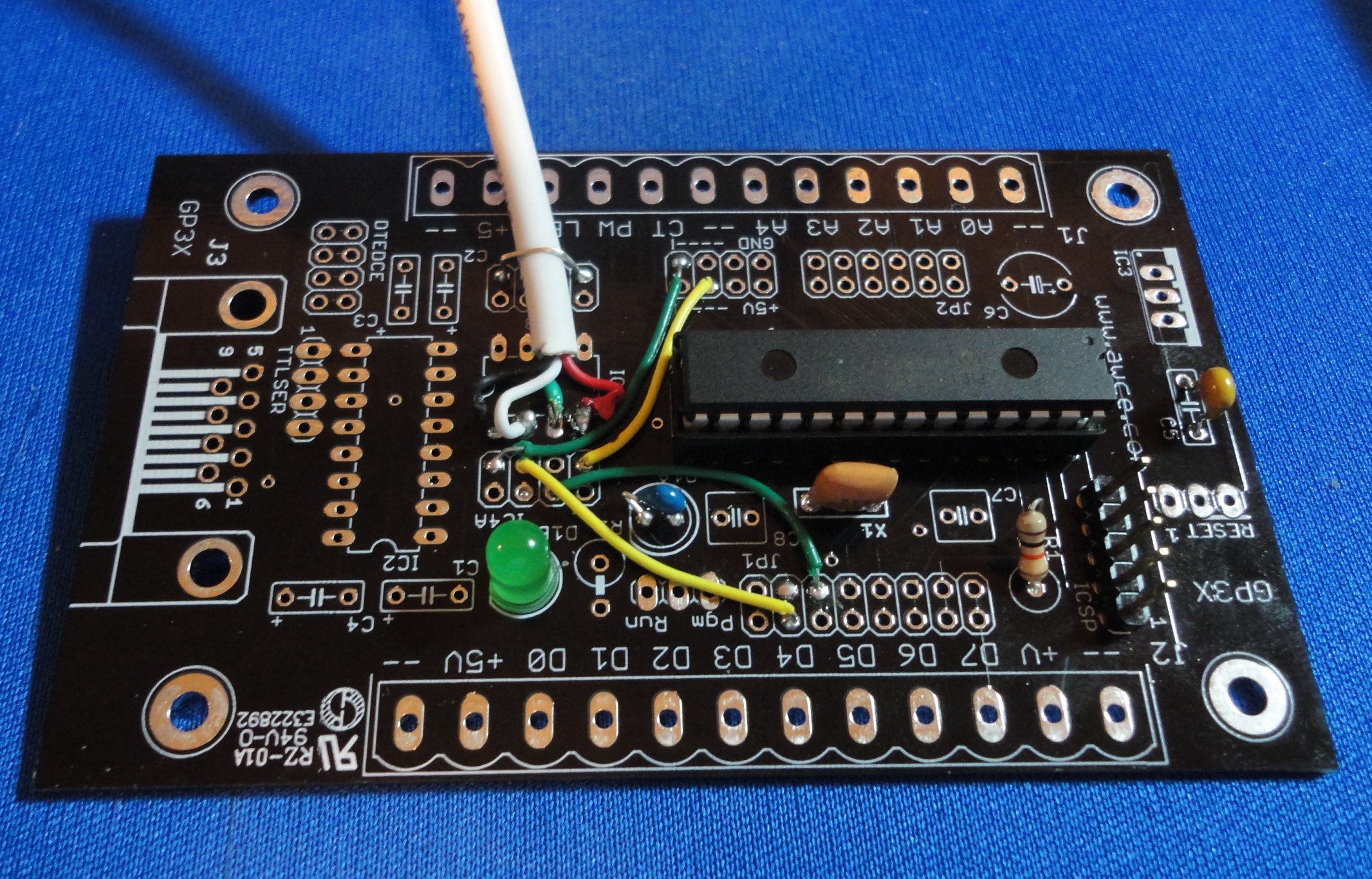
- Solder each wire into the IC4 footprint starting with red in pin 1, green in pin 2, white in pin 3, and black in pin 4.
- Lay the cable flat on the board and use a piece of wire (saved from R1, for example) to form a loop through any two holes in IC4B. Pull tight and solder to form a strain relief for the cable (see photo above).
- Note that IC4A has a pair of holes that correspond to the 4 pins of IC4. Connect pin 1 (either hole in IC4A;connects to red) to any of the +5V holes near the pin marked A4 on J1.
- Connect pin 2 (connects to green) to either of the third pair of holes in JP1. The row of pins you want is between D4 and D5 of J2.
- Connect pin 3 (connects to white) to either of the second pair of holes in JP1. This row of pins is near D4 on J2.
- Connect pin 4 (black) to any of the GND holes near A4 on J1.
- (optional)Install a 5V LED in the D1B holes. Connect a wire to the R2 hole that has a circle around it. The other end of the wire can connect to any pin where you want an LED output.
- (optional)Install a 5 pin header at ICSP to connect a PICKIT or ICD programmer/debugger. (Note that you do need some sort of PIC programmer that can handle the PIC18F2550.)
How Can I Get One?
You can get a bare board, or a kit of parts. Either way, you get the example code (which requires the free Microchip USB stack and the Microchip C18 compiler, which is available in a free version).For now these are shipped with the general GP3 documentation, so be sure to bookmark this page. The below is a special introductory price and may not last!
Add to Cart Complete kit (soldering required) $26.95 each
Add to Cart Board only $12.95 each
Site contents © 1997-2018 by AWC, Houston TX (281) 334-4341