
AWC Electronics - PAK-IX PID
Years ago I worked for a process control consulting company. They had lots of smart chemical guys that could figure out, for example, how to make a factory make more plastic. I remember one time they were able to take the smell out of a plastic which let the client sell more plastic at a higher price.
The cornerstone to controlling chemical processes is the PID (proportional, integral, derivative) controller. A PID compares some value with a set point and generates an output that will -- over time -- bring the value to the setpoint value (or, at least, minimize the error so that the value hovers around the set point).
There are many approaches to the PID algorithm, and discussing yours is a great way to start a fight in a room full of chemical engineers. However, this month I'm going to show you an extremely simplified PID controller that uses a Basic Stamp and a PAK-IX. I'm sure the algorithm won't knock the socks off of anyone who knows a lot about the PID, but it does make a nice example of how the PAK-IX can read analog data, process it using floating point math, and produce results you wouldn't think you could do with a Stamp.
The Circuit
The PAK-IX interfaces with the Stamp using only two wires.
The SIN and SOUT pins connect together. A 4.7K pull up resistor attaches to the pins and this constitutes the data line you connect to the Stamp (pin 15 in the code). The CLK line connects to another Stamp pin (pin 14 in this program, although you can easily change either pin number, of course).
Tie ENABLE/BUSY and RESET high. Also, connect a pull up resistor to BUSY/MODE. The three-terminal resonator has its outer pins connected to RES1 and RES2. The center pin goes to ground. Of course, Vss goes to ground and Vdd goes to 5V.
That's the basic connections for the device. For this month's project I connected an RC circuit to pin 1 of the Stamp. This lets me output a value that corresponds to the control signal. I measure the "process value" at AD0 of the PAK-IX. The code, then has to accept a set point (in 1/10 volt units) and figure out how to adjust the 0 to 255 PWM value to reach the set point.
Of course, you could just compute the value, but what if you have an arbitrary network connected to the output. Then it might not be so simple. For example:
The values for R1 and C1 are not critical. Start without R2 and then add it after you've seen the set up work on the easy case.
Of course, you could just as easily use a PAK II if you had an external measurement and didn't need the PAK-IX's A/D converter. A PAK-I would work too, although the code below uses more memory than the PAK-I has, so it would require some changes.
About PIDs
A PID operates on a cycle. The algorithm compares the measured value (the process value) to the set point and computes the error (just the difference between the process value and the set point). Then, the algorithm computes an output value based on this error. There are three terms to the computation. Each term has a "gain" or coefficient that determines how much each term contributes to the final result. Gains can be fractional or even negative.
The three terms are:
| Proportional - Just the gain times the error. A big error produces a big change in output. Negative gain reverses the action of the PID. | |
| Integral - This is the integral of the error with respect to time. The integral action causes the output to "build up" towards the correct result. | |
| Derivative - This term looks at the change in error. So a rapidly changing error produces more output (or less, if the gain is negative) than a slowly changing error. This term is often useful for retarding the output to avoid overshoot. |
There are many variations on this theme and this is a constant source of debate among those who care about such things. For example, some algorithms examine the rate of change of the process value, not the error. There are also refinements. For example, suppose you select a 4V set point in the circuit above and then adjust R2 so that R1 and R2 (and the PAK-IX's input resistance) forms a 4:1 voltage divider. Now the Stamp has to produce 16V to hit the set point. It can't do that (not without external hardware) so the PID "winds up". That is, the output will go to 255 (5V) and stay there. The integral then will build up over time until R2 is set to a more reasonable value. The problem is, the longer the wind up, the longer it takes for the I term to drift back down to a realistic value. To prevent this, many controllers incorporate "anti-reset windup" which stops the integral from building up when the PID is at its output limit.
You can find a very technical description of the PID at http://www.engin.umich.edu/group/ctm/PID/PID.html. Probably the most useful thing there is this table:
|
CL RESPONSE |
RISE TIME |
OVERSHOOT |
SETTLING TIME |
S-S ERROR |
|
Kp |
Decrease |
Increase |
Small Change |
Decrease |
|
Ki |
Decrease |
Increase |
Increase |
Eliminate |
|
Kd |
Small Change |
Decrease |
Decrease |
Small Change |
So, you can see that if the response overshoots (that is, goes past the set point) you should decrease the derivative gain.
Acknowledgement: Thanks to Beau and Tom Senyard who taught me everything I might know about this when I worked for them at Quad-S. Whatever I'm wrong about is my misunderstanding, not theirs.
A Visual Look
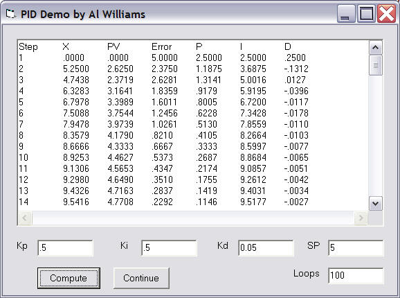
To help you visualize the results of the Stamp algorithm, I wrote a simulation in Visual Basic. The program has a built in function that simulates the external network (in this case, a 50% voltage divider). You can see in the chart below that the yellow line is the error. It drops, zig zags, and then drops again. The error eventually settles at 0.
 Click this thumbnail to see the whole graph.
The interesting part is at the start of the graph, so I've zoomed in on it:
 Click on this thumbnail to see the whole graph.
This was run with gains of .5 (P), .5 (I), and .05(D) for no good reason. Of course, since we "know" the transfer function of the external network, we could "precalculate" the gain, but that's no fun and isn't very useful when the network characteristics are unknown.
Note that a real PID accounts for the time each sample represents. To keep things simple, I'm assuming one second for each loop. You'd have to modify the Stamp code to make it delay a second between measurements if you wanted the timing to be accurate.
You can download my Visual Basic files if you like, although I'll warn you that this was a quick and dirty program so don't expect a whole lot.
The Stamp Code
While I suppose you might be able to code an integer-only PID, it certainly doesn't appeal to anyone I've talked to. With a PAK-IX you can acquire analog values and do the floating point math, so it is a natural for PID applications.
My entire code is below, but there are a few parts that are very interesting.
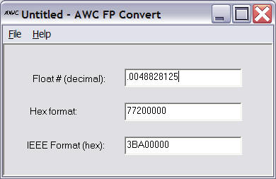
To start, notice that the Stamp program uses several different ways to load numbers into the PAK. For constants (like .0048828125, the conversion factor for counts to voltage), the program loads a special hex number that represents this decimal number:
fpxhigh=$7720 ' .0048828125 (EU constant)
fpxlow=0
gosub floadx
This number is from FConvert (supplied with the PAK):
However, I wanted to make the set point easy to change. So the Stamp treats the set point as a decimal number from 0 to 50 where 50 is 5.0V. So the units are 1/10 volt steps. It is easy to load an integer into the PAK, convert it into floating point, and then divide by 10 to get the correct set point:
fpx=33   ' Set point is 3.3V
gosub floadint

fpxhigh=$8220  ' constant for 10
fpxlow=0
gosub floady ' y=10
gosub fdiv ' now x = "real set point"
Also, to prevent a lot of overhead loading frequently used numbers (like the loop gains), the code stores nearly everything in the PAK-IX's registers. Then it recalls them which is faster than loading them (two output bytes instead of five, plus no waiting overhead). To make the code more readable, the program "names" the registers. For example, here's how the program handles the set point:
sp con 3
.
.
.
fpx=33
gosub floadint

fpxhigh=$8220
fpxlow=0
gosub floady ' y=10
gosub fdiv ' now x = "real set point"
fpx=sp
gosub fsto  ' this puts the set point in register #3
.
.
.
fpx=sp
gosub frcl
gosub fsub ' X=SP-PV
This is a useful trick which not only makes things faster, but saves variable space in the Stamp as well.
Notice that while the code is long, everything after "' END OF TEST CODE ----" is the standard library shipped with the PAK-IX.
Start with no variable resistor and verify that the output moves towards 3.3V and then settles down. Then you can try shunting the output with a fixed or variable resistor to see the effect. Remember, if you force the PID to either extreme it will wind up -- you can't make the Stamp put out more than 5V or less than 0V! The feedback network, of course, could be anything. A transistor or op amp circuit would give you some practice at tuning real hard-to-predict loops.
Here's the code:
'{$STAMP BS2p}
' This is a very simple example PID
' controller for the PAK-IX
' The Stamp generates a PWM train
' which is fed through an unknown RC filter
' the PAK-IX reads the corresponding
' voltage and controls the output
' to achieve a setpoint
' The PID is very crude -- no anti reset windup or
' derivitive filtering although you could
' add these features if you wanted to do so.
' For simplicity, the loop assumes T=1
' however, in real life you'd probably
' want to put a real delay in the loop
' and modify the algorithm accordingly

' This software is provided "AS IS"
' with no warrantee of its fitness
' for a particular purpose
' (c) 2002 by AWC

' Change these to suit your setup
datap con 15 ' Data pin (I/O)
datapin var in15
clk con 14 ' Clk pin (output)

' Enable/Busy if used (not used in example schematic)
en con 8
EnableBit var in8


' Constants for options
FSaturate con $80
FRound con $40

'input en ' remove this line if not using Enable/Busy
output clk
output datap

fpstatus var byte ' FPSTATUS - last result code
fpx var word ' Integer used by some routines
fpdigit var byte ' Digit returned from DIGIT
fpxlow var word ' The X register low & high
fpxhigh var word
fpb var byte ' Temporary byte
' The X register in bytes
fpxb0 var fpxlow.lowbyte
fpxb1 var fpxlow.highbyte
fpxb2 var fpxhigh.lowbyte
fpxb3 var fpxhigh.highbyte


gosub freset ' always reset!

' TEST CODE -- REPLACE WITH YOUR OWN

fpx=$40
gosub FOption ' set RND
i var word


x var byte ' output variable

' floating point variables on the PAK
intg con 0
err con 1
lasterr con 2
sp con 3
kp con 4
kd con 5
ki con 6
euk con 7
temp con 8

' initial conditions
x=0 ' no output
fpxhigh=$7720 ' .0048828125 (EU constant)
fpxlow=0
gosub floadx
fpx=euk
gosub fsto ' store EU constant
gosub fzerox
fpx=intg
gosub fsto ' 0 integral
fpx=lasterr
gosub fsto
fpxhigh=$7F40 ' 1.5
fpxlow=$0000
gosub floadx
fpx=kp
gosub fsto ' kp=1.5
fpx=ki
gosub fsto ' ki=1.5
fpxhigh=$7975
fpxlow=$C28F ' kp=.03
gosub floadx
fpx=kp
gosub fsto

' Load set point in 1/10 volts as an integer
' as though the Stamp had read it from a keyboard
' or computed it from a pot, etc. So 33 = 3.3V
fpx=33
gosub floadint

fpxhigh=$8220
fpxlow=0
gosub floady ' y=10
gosub fdiv ' now x = "real set point"
fpx=sp
gosub fsto

debug "Setpoint = "
fpx=4 ' display
gosub fdump
debug cr


pidloop:
' Output to our "valve" this is the control output
pwm 1,x,1000

fpx=euk
gosub frcl
gosub fxtoy ' Y = euk

' read two A/D samples
fpx=0 ' channel #
fpb=2 ' # of samples
gosub fa2d
gosub fmult ' convert to volts
debug "PV="
fpx=1 ' display
gosub fdump
debug " "
gosub fxtoy
fpx=sp
gosub frcl
gosub fsub ' X=SP-PV
fpx=err
gosub fsto ' store error
gosub fxtoy
fpx=intg
gosub frcl
gosub fadd ' intg=intg+error (assume T=1)
fpx=intg
gosub fsto
gosub fxtoy
fpx=ki
gosub frcl
gosub fmult ' X=integral term
fpx=temp
gosub fsto ' put it away
fpx=lasterr
gosub frcl
gosub fxtoy
fpx=err
gosub frcl
gosub fsub ' compute (error-error0)
gosub fxtoy
fpx=kp
gosub frcl
gosub fmult ' compute deriv. term
gosub fxtoy
fpx=temp
gosub frcl
gosub fadd ' add to integral term
fpx=temp
gosub fsto ' put it back
fpx=err
gosub frcl ' get error term again
fpx=lasterr ' and store it in last error
gosub fsto
gosub fxtoy ' then multiply by kp
fpx=kp
gosub frcl
gosub fmult
gosub fxtoy
fpx=temp
gosub frcl
gosub fadd ' add all terms together
'lets add .5 to make sure we round OK
fpxhigh=$7E00
fpxlow=0
gosub floady
gosub fadd
' need to clamp output to 0-255
gosub fint
x=0 ' guess that answer is negative
if fpxhigh.bit7=1 then isetx
' clamp anything >255 ($FF)
x=$FF ' guess that it is >$FF
if fpxhigh<>0 or fpx>$FF then isetx
' no, it wasn't >$FF so set it for real
x=fpx
isetx:
debug "Output=",dec x
debug cr
goto pidloop
end


' END OF TEST CODE ----


' Reset the Pak9
FReset:
LOW DATAP
LOW CLK
HIGH CLK
HIGH DATAP
LOW CLK
pause 50 ' wait for reload
return

' Wait for enable - not used in example
' but if you use hardware enable, this is the code you need
FBsyWait:
if EnableBit=0 then FBsyWait
return

' Wait for +,-,*,/,INT,FLOAT, & DIGIT
Fwaitdata:
input DATAP
if DATAPIN=1 then Fwaitdata
return


' A/D
fa2d:
SHIFTOUT DATAP,CLK,MSBFIRST,[$29,(fpb-1)<<4+fpx] ' a/d
goto fpstat

' Configure A/D
fa2dconf:
SHIFTOUT DATAP,CLK,MSBFIRST,[$28,fpx]
return

' EEPROM storage
festo:
SHIFTOUT DATAP,CLK,MSBFIRST,[$2A]
goto fpstats

' EEPROM recall
fercl:
SHIFTOUT DATAP,CLK,MSBFIRST,[$2B]
goto fpstats


' poly fpb=register, fpx=degree
fpoly:
shiftout datap,clk,msbfirst,[$27,(fpx-1)<<5+fpb]
goto fpstat


'Change sign
FChs:
fpb=10
FSendByte:
Shiftout datap,clk,MSBFIRST,[fpb]
return

'Absolute Value
FAbs:
fpb=17
goto FSendByte

' Store to register in FPX (0-23)
FSto:
fpb=18
fstox:
gosub FSendByte
fpb=fpx
goto FSendByte

FRcl: ' Recall from register FPX
fpb=19
goto fstox


' Store0 -- compatible with PAK1
FSto0:
fpb=18
fstx:
gosub FSendByte
fpb=1
goto FSendByte

'Store1 -- compatible with PAK1
FSto1:
fpb=18
fstx1:
gosub FSendByte
fpb=2
goto FSendByte

'Rcl0 - Compatible with PAK1
FRcl0:
fpb=19
goto fstx

'Rcl1 ' Compatible with PAK1
FRcl1:
fpb=19
goto fstx1

' Load X with fpxhigh, fpxlow
FLoadX:
Shiftout datap,clk,MSBFIRST,[1,fpxb3,fpxb2,fpxb1,fpxb0]
return

' Load Y
FLoadY:
Shiftout datap,clk,MSBFIRST,[2,fpxb3,fpxb2,fpxb1,fpxb0]
return


' Load X with 0
FZeroX:
Shiftout datap,clk,MSBFIRST,[1,0,0,0,0]
return

' Load Y with 0
FZeroY:
Shiftout datap,clk,MSBFIRST,[2,0,0,0,0]
return

' Load an integer from FPX to X
FLoadInt:
Shiftout datap,clk,MSBFIRST,[1,0,0,fpx.highbyte,fpx.lowbyte]
' Convert from Int
Shiftout datap,clk,MSBFIRST,[7]
goto fpstat

' to int
FInt:
Shiftout datap,clk,MSBFIRST,[11]
gosub Fwaitdata
Shiftin datap,clk,MSBFIRST,[fpstatus]
if fpstatus<>0 then FInterr


' Read the X register
FreadX:
fpb=3
gosub FSendByte
ShiftIn datap,clk,MSBPRE,[fpxb3,fpxb2,fpxb1,fpxb0]
fpx = fpxlow
FInterr:
return


' Swap X and Y
FSwap:
fpb=4
goto FSendByte

' Load X with pi
FPI:
Shiftout datap,clk,MSBFIRST,[1,$80,$49,$F,$DB]
return

' Load X with e
Fe:
Shiftout datap,clk, MSBFIRST,[1,$80,$2D,$F8,$54]
return

' X=X*Y
FMult:
fpb=12
fpstats:
gosub FSendByte
fpstat:
gosub FWaitdata
Shiftin datap,clk,MSBPRE,[fpstatus]
return ' status

' X=X/Y
FDiv:
fpb=13
goto fpstats

' X=X+Y
FAdd:
fpb=15
goto fpstats

' X=X-Y
FSub:
fpb=14
goto fpstats

' Get Digit (fpx is digit #) return in fpdigit
FGetDigit:
Shiftout datap,clk,MSBFIRST,[5,fpx]
Fgetdigw:
gosub fwaitdata
ShiftIn datap,clk,MSBPRE,[fpdigit]
return


' Dump a number fpx is # of digits before decimal point
' Assumes 6 digits after decimal point
' Change $86 below to change digits after DP
' So $83, for example, would be 3 digits after DP
FDump:
fdj var byte
fdnz var bit
fdjj var byte
fdjj=fpx
fpx=0
fdnz=0
gosub FgetDigit
' Remove this line to print + and space
if fpdigit="+" or fpdigit=" " then Fdumppos
Debug fpdigit
Fdumppos:
for fdj=1 to fdjj
fpx=fdjj+1-fdj
gosub FgetDigit
if fpdigit="0" and fdnz=0 then FdumpNext
fdnz=1
Debug fpdigit
Fdumpnext
next
Debug "."
for fpx=$81 to $86
gosub FgetDigit
Debug fpdigit
next
return

' Set options in fpx
' $80 = saturate
' $40 = round
FOption:
Shiftout datap,clk,MSBFIRST,[$10,fpx]
return

' Copy X to Y
FXtoY:
fpb=$17
goto FSendByte

' Copy Y to X
FYtoX:
fpb=$18
goto FSendByte

' PORT A Routines
' Set I/O Direction (dir in fpx)
IODir:
Shiftout datap,clk,MSBFIRST,[$14,fpx]
return

' Write bits in FPX to I/O port
IOWrite:
Shiftout datap,clk,MSBFIRST,[$16,fpx]
return

' Read bits to FPX
IORead:
fpb=$15
gosub FSendByte
Shiftin datap,clk,MSBPRE,[fpx]
return

' PORT B Routines
' Set I/O Direction (dir in fpx)
IODir1:
Shiftout datap,clk,MSBFIRST,[$94,fpx]
return

' Write bits in FPX to I/O port
IOWrite1:
Shiftout datap,clk,MSBFIRST,[$96,fpx]
return

' Read bits to FPX
IORead1:
fpb=$95
gosub FSendByte
Shiftin datap,clk,MSBPRE,[fpx]
return


' Square Root
fsqrt:
fpb=25
goto fpstats

' Log (base e)
flog:
fpb=26
goto fpstats

' Log (base 10)
flog10:
fpb=27
goto fpstats

' e**X
fexp:
fpb=28
goto fpstats

' 10**X
fexp10:
fpb=29
goto fpstats

' X=X**Y
fpow:
fpb=30
goto fpstats

' X=X**(1/Y)
froot:
fpb=31
goto fpstats

' X=1/X;
frecip:
fpb=$20
goto fpstats


' X=X**2 ; does not destroy Y, but destroys fpxlow/fpxhigh
Fsquare:
gosub fswap ' get y
gosub freadx ' save it
gosub fytox ' y->x
gosub fmult ' x=x*y
gosub floady ' restore old y
return

' Arcsin(X)
FArcSin:
fpb=$A1
goto fpstats

' Arccos(X)
FArcCos:
fpb=$A2
goto fpstats

' ArcTan(X)
FArcTan:
fpb=$A3
goto fpstats

' sin(x)
FSin:
fpb=$21
goto fpstats

' cos(x)
FCos:
fpb=$22
goto fpstats

' tan(x)
FTan:
fpb=$23
goto fpstats
This article is copyright 1999, 2000, 2001, 2002 by AWC. All Rights Reserved.
Site contents © 1997-2018 by AWC, Houston TX (281) 334-4341