
AWC Electronics - Yet Another GP3 Robot
Yet Another GP3/GP3EZ Robot
Robots are a fun way to show off the GP3 and GP3EZ board. The GP-3X has flexible screw terminal mounts so adding it to one of my robot platforms was a piece of cake.
The Platform
Picture coming soon
For the base of the robot I used a Tamiya track kit. This comes with a nice little set of plastic tank tracks (although the orange color is a little flamboyant), two 3V motors, and a gear box for the treads. It also has a battery case with a switch so you can make the treads go forward or backward.
First thing to do is throw away the battery box. You could use it and just keep the switch set in one position, but I figured someone would reverse circuit the battery and fry my electronics, so I replaced it with a standard two cell battery holder. I also put a 9V battery holder in place to power the GP-3X board.
You can build the tracks at two different gear ratios. I picked the lower gear ratio figuring I wanted to haul batteries, not necessarily go fast. The construction is easy once you stare at the instructions for an hour.
There isn't much room on the little piece of wood they have you build the tracks on. So I took two bass wood posts and made uprights and then used a much larger piece of bass wood and made a deck for the electronics. A large hole (courtesy of a step bit and my drill press) lets wires feed down to the motors on the bottom deck.
Motor Control
Because the motors run on 3V, it is dead simple to use 4 IRL520s in an H-bridge configuration to run the motors forward or backwards. That's the top part of the schematic below (you need to build that part of the circuit twice; once for each motor). The FETs are IRL520s, as I mentioned, and the resistors are 100K. They aren't strictly necessary, but it will help to keep the FET gates from blowing from static electricity. NEVER set both motor controls high at the same time. Set one high if you want the motor to go one way. Set the other high if you want to go the other way. Its that simple.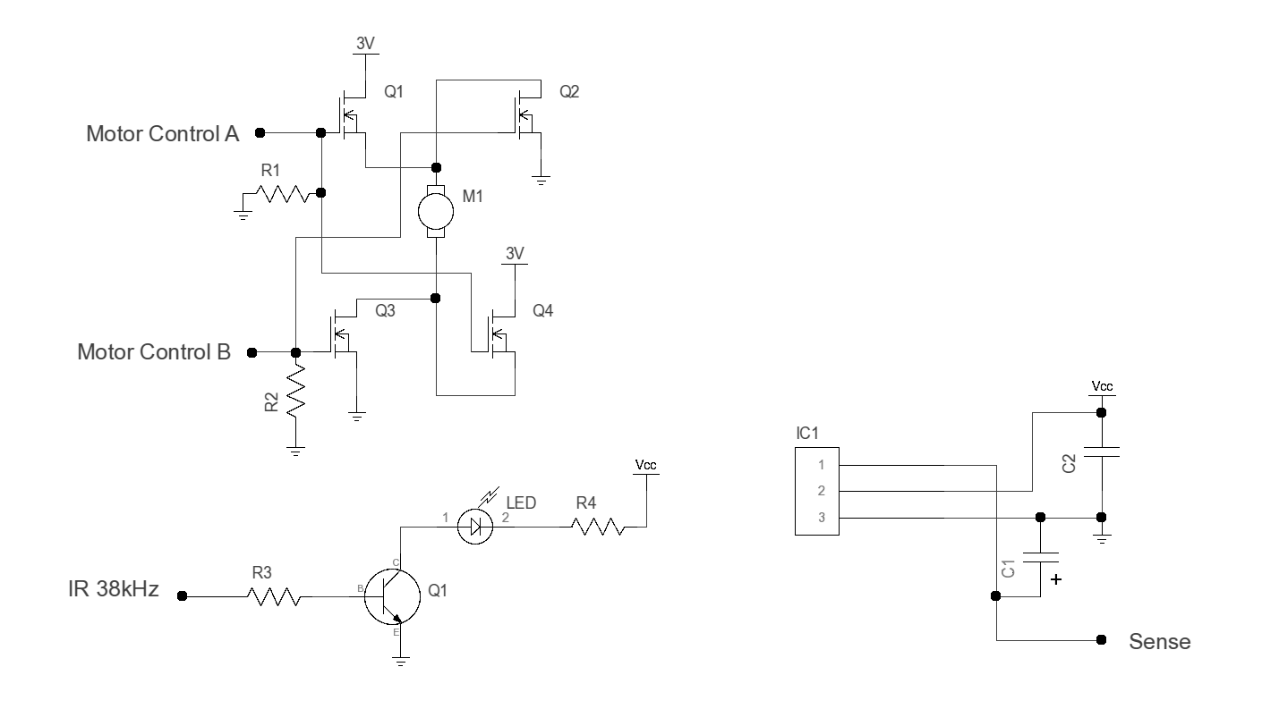
Object Detection
I've often used IR detectors to keep my robots from bouncing on things. The way this works is you modulate an IR LED with a certain frequency, and a sensor can "see" the IR coming from the LED. If you didn't modulate it, the sensor would be prone to things like lighting or flames or other sources of IR.
The PWM output from the GP3 would be perfect for modulating the LED but it maxes out at 32kHz. You can get sensors that are made for 32kHz (and many other frequencies), but 38kHz is more common for historical reasons. I have had some sensors that were "broad" enough to see a 32kHz signal (probably with reduced sensitivity) but some aren't (and lately, they seem to be getting tighter).
So instead of using the PWM output, I decided to just use a regular digital output. I wanted to be able to pulse some power through the LED so I used a 2N2222 (the Q1 at the bottom of the schematic; yes I realize there are two Q1's -- sorry about that). Any small NPN transistor should do here. R3 is 1K and R4 is 50 ohms. You may need to adjust R4 based on your LED. If your LED has a 1.3V drop and figure Q1 has a .7V drop, that's 2V. So R4 will have 3V across it and the current is 3/50 or about 60mA. The duty cycle is low, but you still want a beefy LED or a higher value resistor for R4. You might start with 100 ohms, for example. If you limit the current to within the GP3's capabilities, you could drive it direct (getting rid of R3 and the lower Q1).
So that takes care of the IR output. By the way, you can visualize an IR LED by looking at it with a digital camera or camcorder. Try it with a remote control first and you'll see that most digital cameras will show an IR led that is on as a very bright light flare.
Using the digital output for the LED leads to a problem on the sensor side. The GP3 only does one operation on the digital I/O lines at a time. So you can't tell it to produce a frequency on one pin and read the state of another pin at exactly the same time. With the PWM output, that runs all the time, so you don't have that problem. But we aren't using the PWM output so the LED can run at 38kHz. So what to do?
The answer is simple. C1 is a 3.3uF capacitor hooked up to the output of the sensor. By the way, IC1 (the sensor), can be any 38kHz IR module, but double check the pin out with the data sheet. They are not all the same! On the schematic, pin 1 is the output, pin 2 is +5V, and pin 3 is ground, but your device could be different! Anyway, C1 makes the sensor take a little longer to switch states. The sensor pulls the pin to ground when it senses IR, but C1 will hold it high just a little bit longer. We don't really care about that, because when the sensor sees IR we won't be looking at the sensor. What we care about is when the IR stops. That's when we will look at the sensor. The sensor tries to go back to a logic 1, but the capacitor holds the pin low for just a little bit longer -- long enough for the GP3 to read the pin and see that the sensor was seeing IR.
Connections
If you build two H-bridges you'll have 4 motor control wires. The A and B wires from one bridge I connected to D0 and D1 of the GP3. The other two went to D6 and D7. The IR 38kHz signal I pulled off of D5 and I sent the sense input to D2. Obviously, the grounds need to go together from both the 3V battery and the 9V battery. Vcc is 5V coming from the GP3 board.
Software
I used the GP3EZ software to get the robot running. The first thing I did was just hardwire the H-bridge signals to test the motors. Satisfied that they were working I turned off the 3V battery until I had the software working so the thing didn't crawl all over my desk.
Turning on the motor control pins with GP3EZ is really simple. The only tricky part was making it turn when it sees something. I arranged the program so that it turns the onboard LED on when it "sees" some reflected IR so that way I could test the whole thing with the motors off. Keep in mind that with GP3EZ you can test and debug your code on the PC with the cable (serial or USB) plugged in. Then you can download the code and disconnect. That's when I turned the motors back on, and the robot did what it was supposed to do. Here's the code:
| Step # | Tag | Condition | Action | Next | Notes |
| 1 | (Set I/O = OOIIIIOO) Always |
LED Off Out: 00XXXX00 | Set up output pins for robot P0 = Left 0 P1 = Left 1 P6 = Right 0 P7 = Right 1 | ||
| 2 | Start | Always |
LED Off Out: 000XXX00 | Loop here | |
| 3 | Always |
Tone: pin 5 @32767Hz for 500 | Burst of PWM | ||
| 4 | Input: XXXXX0XX |
LED On Out: 01XXXX01 | Object | Check for something in front of us (if so nudge backwards a bit and go to object) | |
| 5 | Always | Out: 10XXXX10 | Go forward | ||
| 6 | After 750 ms | Start | Wait a bit and repeat | ||
| 7 | Object | After 125 ms | Out: 10XXXX01 | Uh oh... Turn | |
| 8 | After 500 ms | Start | Turn a bit and go back to start |
Step 1 just turns the motor control pins to outputs and sets them to zero. That stops the motors. The LED is turned off too. Step 2 is the start of the main loop. It is basically a repeat of step 1 but does not reset the I/O pins. This is probably not strictly necessary -- you could probably just mark step 1 as Start and delete step 2, but because of some experimenting I was doing, this is how the program is.
Step 3 sends a 500mS burst to the IR LED. The program needs to check the sensors immediately afterwards because the capacitor won't hold the line for long. So that's what step 4 does. If there is a signal, the step executes. It turns on the LED and turns the motors to reverse (01XXXX01). Then it goes to the "object" statement (step 7). If it does not sense anything, nothing happens and the program goes to step 5. That just moves forward, waits a bit (step 6) and then goes back to Start (step 2).
If it did see something and goes to Object, the code there, sets the tracks to go in opposite directions for a bit to turn and then jumps back to Start to repeat the whole process.
You may want to play with the delay in step 6 depending on your IR setup. You don't want the robot to travel further than it can see. So if your IR sensor is sensitive to, say, 8 inches, the delay should be long enough for the robot to move no more than 8 inches. That way you won't run into something you didn't see. The exact range will depend on how much power you use in the LED, the LED you use, the sensor you use, etc. You may also need to block the sensor with some cardboard or something (I used antistatic foam) to keep light from the LED from directly reaching the sensor. You want the sensor to only see IR bouncing off an object.
That's it! A simple robot that takes a few hours to build. If you try to duplicate it, don't forget that the H-bridges shown would not be suitable for 12V motors. And keep in mind that there is a wide range of IR sensors and LEDs. You may have to play with C1 and/or R4 to get things working right.
Site contents © 1997-2018 by AWC, Houston TX (281) 334-4341