
AWC Electronics - GP-3 and LabView
Note: LabView is a trademark of National Instruments. AWC is not affiliated with National Instruments in any way.
LabView is a common tool used to work with data acquisition hardware. The GP-3 is a very cost effective board. Can it be used with LabView? You bet.
The GP-3 uses a simple serial protocol to communicate and LabView can handle the serial port through its VISA drivers. Unfortunately, LabView is easiest to use with inefficient ASCII protocols. The GP-3 packs as much data as in can in the smallest space and do it takes a little work to make it work with LabView. Luckily, LabView can hide this complexity with sub-VIs. I've included some useful sub-VIs in this article, and I'll post more as I create them. But once you see how to do it, you should have no trouble making your own sub-VIs for particular GP-3 functions.
There are really two major categories of cases. First, there are commands you send to the GP-3 and you don't expect any answer back. Those are pretty easy, so let's start there. The onboard LED requires a hex 0D to turn on and a hex 0C to turn off (you can find that in the manual). The board requires 57600 baud, 8 bits, one stop bit, no parity, and hardware handshaking.
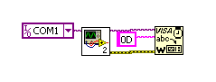
To set up the serial port in LabView requires the "Configure Port" block from the Instrument I/O/Serial palette. However, it is easy to make a sub-VI that knows how to open the GP-3 specifically. So my first step is to use the "Select a VI..." choice from the palette and pick gp3open.vi. This gives me a simple block that looks like a standard LabView serial port opener, but is preconfigured for the GP-3. The only mandatory connections are the name of the serial port and the output "VISA resource name out" will trigger the next step of the sequence.
For simplicity, I'm just going to hardcode "COM1" in as the name of the serial port. In a real instrument I might use a selector to pick a port, but for this simple demo, a string constant will do. To send a command to the board, a standard VISA Write block (also on the Instrument I/O/Serial palette) will do the trick. This block expects a string and for now I'm going to hardcode that as well.
When I right click on the "write buffer" terminal of the write block, I can create a string constant. The problem is, the GP3 doesn't want a string per se. It wants a hex value. But that's ok. Right click on the constant and check "Hex Display." Then type 0D in the box. That's it!
Granted, its a pretty trivial thing, but that little sequence will turn the LED on. Reset the board in PGM mode to make sure the LED's off and run the VI -- the LED should light up. Here's the simple VI shown graphically (the box with the 2 in it is the GP3 open component):
Of course, you might not want to hard code the command into the VI. What if, for example, you wanted the LED to light or not based on a switch? The trick is to compute the command you want into a byte (U8) array and then convert the array into a string. That string will connect to the write block.
The first step is to include a numeric constant and a boolean switch. Right click on the constant and set its representation to U8 (unsigned 8 bit). Then right click again and select hexadecimal on the display format menu. Then enter "C" into the constant. This is the command to turn the LED off. Add another constant and put "D" in instead of "C." Its easy to copy and paste the existing constant so you don't have to reset all the other info -- just change the constant.
On the Programming/Comparison palette is a block named "Select." Add one to your diagram. This block lets you pick one or another value based on a boolean. The "t" terminal goes to the "D" constant. The "f" terminal goes to the "C" constant. The "s" terminal goes to the switch.
The output of the select ought to go to the VISA write block, but it is of the wrong type. First, we need to convert it to an array (granted, an array with one element in it, but still an array). Under Programming/Array is a "Build array" block. You can place it and feed its input from the output of the select block. We only need one item in the array this time, but if we needed more, you can right click on the build array block to expand it using "Add Input" from the menu.
The output of the build array is still not a string, but there is a block in the Programming/String/Conversion palette that converts byte arrays to strings. Add that, and connect the dots. You should have something that looks like this:
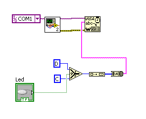
This time use the "Run continuous" button to execute and you should be able to light the LED and extinguish it with the switch on the VI front panel.
What happens if you need to get data back from the GP-3? That's basically the reverse process. You get a string back from the GP-3, convert it to a byte array, and from there you can process it as you like.
As an example, consider the command to read the A/D convert. You send a 30 hex for channel 0, 32 hex for channel 1, etc. Then you get back two bytes: the high byte and the low byte. To get the actual number of counts, you multiply the high byte by 256 (remember not to use a U8 for the 256; use a double so that the result will be a double) and add the low byte.
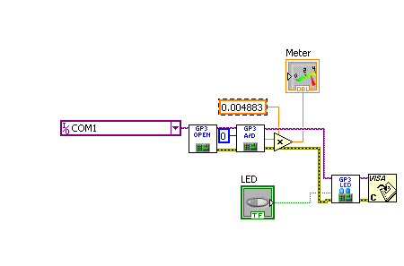
Rather than work through this step by step, here's a sub-VI provided below that reads something from the A/D:
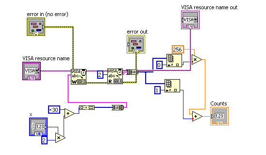
Note that the sub VI exposes some of the same things as a write block (and there is a write block inside). The hex 30 constant is added to twice the port number down at the lower left of the diagram. The result is converted to an array (make sure to force the numbers to U8) and then to a string. The output VISA name triggers the input VISA name of a read block which is set to read 2 bytes (the 2 constant roughly in the center of the diagram). The resulting string is converted to a U8 array. The array index components select items 0 and 1. Item 0 is multiplied by 256 (note it is orange; a double) and added to the low byte (item 1) to get the counts.
Here's an example VI using the two sub-VIs:
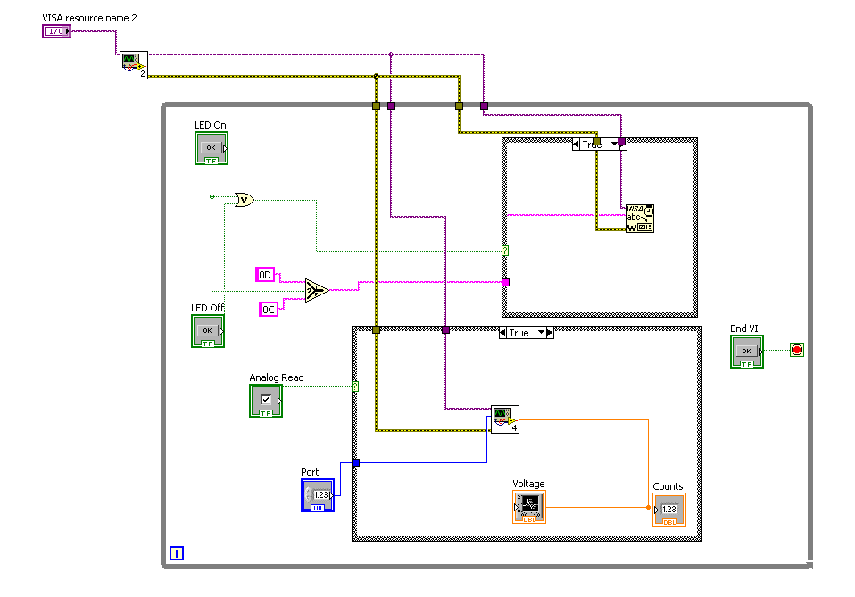
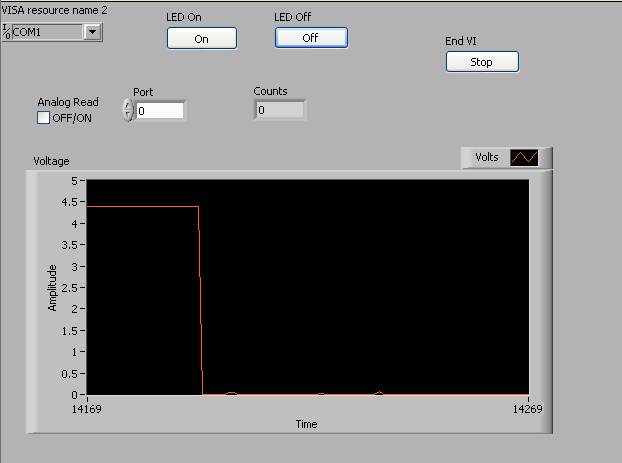
Here, two momentary switches control the LED and almost everything is in a "while"container. It would not do, for the LED control and the A/D reader to run at the same time. So each part is enclosed in a case container so it only executes when the case input is True. An Or gate makes sure that if either button is pushed, the LED code executes. The analog reading is controlled by a check box. Note the raw counts are sent to an indicator and also collected by a waveform recorder. The recorder also has the right constant in it to convert the raw counts to voltage. Here's the front panel executing with channel 0 connected to the LED output:
That's it! You can use these same techniques to send the GP-3 any command you like using constants or computed values. The GP-3 is a very cost effective way to give your LabView virtual instruments real analog and digital I/O.
Download sample GP-3 VIs and sub VIs (updated 14 June 2010)
Example of GP-3 VIs in use.
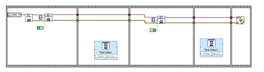
Another example.
Site contents © 1997-2018 by AWC, Houston TX (281) 334-4341