
AWC Electronics - Making the Switch
The Stamp is a great little device and once you have the power to control things so easily, you keep thinking up more things you want to control. I'm really wanting to do the pool, although I keep putting it off. I've thought about automating my thermostat, our aquariums, and the lights in my office.
The only problem is that the Stamp's outputs can't do much in the real world. This isn't a problem with the Stamp per se -- any digital logic device operates at 5V and relatively low current.
For switching DC loads, I have become a firm advocate of power FETs. For example, on our components page you can get IRL520 MOSFETs. These are overkill for most situations, but I find it handy to have one nearly perfect DC switch that covers all of my needs.
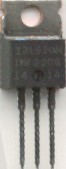
These transistors are in a TO220 case (like a 7805 package). They can handle 100V and 9.2A continuous (you'll need a heat sink if you draw a lot of current). The gate accepts logic level inputs and the on resistance is just over 1/4 ohm! The pulsed current spec is very high (36A).
Granted, if you are making dozens of the same device, you might want to spend some time and find a MOSFET or bipolar transistor that exactly fits your need (and costs less). On the other hand, for simple projects, it is easier to just have these around. They are perfect for driving LED arrays, DC lamps, relays, or motors.
Hookup is very simple. In the picture above the gate is the leftmost pin, the drain is in the center and the source is the rightmost pin. Simply ground the source and connect the drain to the ground side of your load. The gate can connect directly to the Stamp or other digital output. You should put a resistor from the gate to ground to prevent static build up when the circuit is off. If you are worried about power consumption, this resistor can be quite large (1M, for example). However, if you want to minimize switching time, you can make it rather small (10K or lower). This resistor will effectively be the load the Stamp output sees.

When the Stamp output is low, the MOSFET is practically an open circuit. When the Stamp output is high, the MOSFET is more or less a short. If your load is a 12V light bulb, for example, you'd connect one side of the bulb to the drain and the other side to +12V. When the MOSFET turns on (the Stamp output is high) the bulb will light. If you want to drive something inductive (like a solenoid or a relay) you should put a diode across the load to absorb spikes. The banded end of the diode goes towards the + supply and the other end points towards the MOSFET's drain.
The Relay
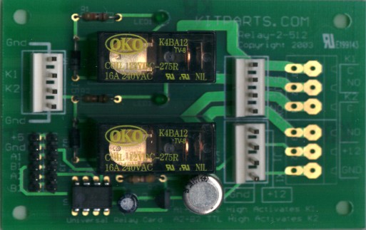
In some cases -- switching AC for example -- relays are still a very viable option. The picture above shows our latest kit -- a universal board that drives two high-current SPST relays. This kit greatly simplifies using relays in your projects. The board accepts a 12V power connection (a 78L05 produces 5V for the board so you don't have to use your own 5V supply).
The board accepts four logic inputs: A1, B1, A2, and B2. To turn a relay on (close its contacts) you have to assert the corresponding A and B inputs. This is useful when you want to provide, for example, a manual enable function. If you ground the A input, for example, the Stamp will be unable to turn the relay on. Setting the input high allows the Stamp (connected to the B input) to control the corresponding relay. Of course, you can always connect the A and B inputs together so that the Stamp simply controls the relay with a single output, if you prefer. In addition, you can connect all the inputs together to form a double pole relay.
The board has built in protection diodes and LEDs that show the state of each relay.
This is a great "building block" to have around for times when you need to switch AC, substitute for an unknown mechanical switch, or you just want your project to have the clacking sound of relays!
The Stamp code below will turn a light (or a motor, or whatever) connected to relay #1. The circuit needs +12V, a common ground with the Stamp and the A1 and B1 inputs connected to Stamp pin P15. The circuit turns the relay on for about 10 seconds of every minute.
You can find out more about the relay kit or read the documentation for it.
Stamp Code
'{$STAMP BS2}
RELAY CON 15
MLoop:
HIGH RELAY
PAUSE 10000 ' 10 seconds
LOW RELAY
PAUSE 50000  ' 50 seconds
GOTO MLoop
Site contents © 1997-2018 by AWC, Houston TX (281) 334-4341