
AWC Electronics - Using the GPMPU40
Our GPMPU40 kit allows you to easily configure a development board for practically any DIP packaged microcontroller. The standard kit allows you to rapidly make connections between a 5V power supply, a reset circuit, an RS232 converter, and even a programming and breadboard connector. You can even change the serial port from DTE to DCE! However, once you've soldered the board together, you've pretty much locked its configuration unless you want to unsolder the configuration jumpers, which is no fun.
Of course, if you have a specific microcontroller in mind, that's not a problem. You configure the board once and that's it. But if you are switch chips like I do (either for consulting jobs, writing articles, or just experimenting with a new chip) you want something you can quickly reconfigure. The GPMPU40 can do handle the job. In fact, we've introduced a new "flavor" of the GPMPU40 especially designed for this situation. Here's how it is different from the standard kit:
| Four rows of machine pin headers let you plug any chip you like into the socket area. Plug in a 40 pin DIP or any combination of smaller chips on .6 inch or .3 inch centers. So you can plug in, for example, a 24 pin Basic Stamp II and an 8 pin serial EEPROM. | |
| All configuration jumpers have pin headers installed. | |
| The kit includes mating connectors so that you can set up different configuration options without soldering. |
If you prefer, you can also use a wire wrap tool to make temporary connections between the header pins. Either way, it is a snap to reconfigure the board quickly for new chips.
An Example
As an example, I had the nice folks at Maxim send me two DS89C420 microcontrollers. Maxim is very generous with free samples (Microchip is good too), so these two chips didn't cost me a cent. What's an 89C420? It is a high speed 8052 processor that has flash memory, single-cycle execution, and runs at up to 33MHz. Since it is essentially an 8051/8052 processor, it works well with SDCC, the freeware C compiler. The chip has its own RS232 boot loader, so it is perfect for use with the GPMPU40.
There are several considerations when you want to reconfigure the GPMPU40 for a new processor:
| Power connections - Pin 40 is +5V and pin 20 is ground | |
| Clock - A clock element connects to pins 18 and 19; I used a 20MHz resonator in the GPMPU40's crystal socket | |
| Reset - Pin 9, see below | |
| RS232 - Pin 10 is the RS232 receiver and pin 11 is the transmitter; |
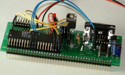
You simply place jumpers to connect the right pins (see the picture above -- you'll get the idea). Since we will hook the board to a PC to program it, we need a DCE serial port, so the JP5 jumpers connect R to 3 as well as T to 2 (DTE would connect R to 2 and T to 3).
The only difficult part to this processor is the reset connection. That's because the 8051/8052 parts have a positive reset! The reset circuit on the GPMPU40 is designed to ground the reset pin. The DS89C420 lets you leave the reset pin floating (or grounded) to run the chip and expects you to pull the line high for a reset. Since the pin can float, you can just leave it disconnected. Alternately, you can wire a reset jumper on the breadboard attached via the 40 pin edge connector. Finally, you could install a reset jumper in the holes for T1, the reset controller on the GPMPU40 board (which is not used otherwise). One pin of T1 goes to 5V and another connects to the RST holes, so it is easy to put two header pins in these holes, if you desire. However, the usual reset switch will not be effective. Of course, you could cut the trace going to the reset switch and rewire it, if you really wanted to use the built in switch.
Using SDCC
Here's a simple program written in SDCC (or download the ihx file, if you'd rather not download the compiler, at which point you might just skip to the next section):
#include <8052.h>
#include <stdio.h>

#define BAUD_9600 0xFFBF
void serial_init(unsigned reload)
{
  T2CON=0x30;
  RCAP2L=reload & 0xFF;
  RCAP2H=reload>>8;
  TL2=reload & 0xFF;
  TH2=reload>>8;
  TR2=1;
  SCON=0x50;
  TI=1;
}

void putchar(char c)
{
 while(!TI);  /* wait for ready */
 TI=0;
 SBUF = c;
}

char getchar(void)
{
 char c;
 while(!RI);
 RI =0;
 c = SBUF;
 return SBUF;
}

void main()
{
   serial_init(BAUD_9600);
   printf("Hello! %d\n",BAUD_9600);

// echo next character, so if you enter a, the CPU sends b, etc.
   while (1) { putchar(getchar()+1); }
}
Compiling this program is easy (assuming it is named test8052.c):
sdcc test8052.c
That command produces test8052.ihx and you can follow the steps below to download the program.
Programming
Dallas provides their Microcontroller Toolkit (MTK) as a free download. This, along with an 8052 assembler or compiler is all you need. I had SDCC already installed, so I used that. When you start MTK2, you have to select the device you want:
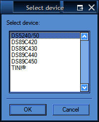
Pick DS89C420, in this case, and press OK. You need to set the chip to boot loader mode. To do that, I connected reset (pin 9) to +5V with one of the board's jumpers. Then I used wires on the breadboard to tie pin 29 (PSEN) to ground and also pin 31 (EA) to ground. This sets up the boot loader mode.
You can use the MTK's Option | Configure Serial Port command to pick the serial port and baud rate you want to use. The chip autodetects the baud rate, so with a 20MHz crystal you can probably set a pretty high baud rate. I stuck with 9600 baud, just to avoid trouble. Next select Target | Open COM1 at 9600 Baud and then select Target | Connect to Loader. You should see something like this:
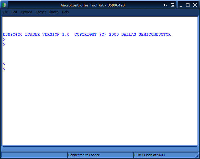
Of course, you have to have power to the board, the COM port has to be working, connected, and not otherwise in use, and you have to have the Reset, PSEN, and EA pins connected as described above.
When I first did this, it all worked! However, when I tried to program a second program into the chip, it failed. After a little head scratching, I figured out that you have to erase the chip before reprogramming. To do this, you mysteriously enter K and Enter in the MTK window! I never found this explicitly documented that you had to do this, but failing to erase causes a cryptic error message (in particular: Error writing file: expected G and received P).
Once the chip is blank, you can use the File menu to pick a hex file (SDCC generates IHX files which are OK) and download it to the chip. When you are done, remove the breadboard wire that is grounding PSEN (I just pull the wire out of the ground socket) and move the EA wire from ground to +5V. Then you can remove the reset jumper from the +5V bus and the chip should run your program.
Wrap Up
Using the GPMPU40 has always been a smart way to have one development board for any processor you want to use. Now with the universal kit, you can rapidly prototype with the best chip for the job instead of using the chip you happen to have tools for. This is also the perfect setup for school labs, consultants, or anyone interested in a wide range of chips. The GPMPU40 board's manual shows the connections for several popular processors, including the Basic Stamp, several PICs, AVR processors, and the Ubicom SX. However, as you can see, it is easy enough to adapt any given processor to the board.
Site contents © 1997-2018 by AWC, Houston TX (281) 334-4341