
AWC Electronics - GP3 for Arduinio
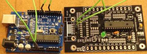
GP3/A connected to an Arduino (note: screw terminals included in kit not installed in this picture; Arduino not included)
The GP-3 has always been a great way to add real-world I/O to your PC, but now you can bring that same power to the Arduino. Although you can use any GP-3 board with an Arduino, you don't need the components required for connection to a PC. This kit has just what you need to connect the GP-3 to an Arduino (or other 5V TTL-level serial device). Note: Also available in a 3.3V version.
The GP-3 has an impressive slate of features including:
- 8 general purpose I/O lines (digital input/output with special features like PWM or pulse output)
- 5 10-bit A/D inputs (separate from digital pins)
- 1 hardware PWM output (operates continuously)
- 1 hardware counter input (operates continuously)
- 1 LED under software control
- EEPROM for storing configuration or serial numbers (256 bytes)
- Arduino library can be used with SoftwareSerial library or any compatible library (such as AltSerial). Download Documentation (included in download)
Simply connect 4 wires (power, ground, RX, and TX) between your Arduino and the GP3/A and you'll have unmatched real world I/O capability using a time-proven and efficient board. The simple library will have you up and running in no time.
For more details, read the main GP3 page or read the manual.
What resources are available?
You can find all the software and documentation for the GP-3 in the GP-3 Center.
Example Code
This simple example flashes an LED and reads an analog input from the GP3:
#include <SoftwareSerial.h>
#include <GP3.h>

/* Example program for GP3 Control with Arduinio
 * Al Wiliams -- http://www.awce.com/gp3.htm
 *
 * Example V1.0 for use with library V1.0
 */

/* The GP3 library uses SoftwareSerial by default so you need to include it
   However, you can initialize it with a stream if you prefer so you should
   be able to use Serial1 or AltSoftSerial, etc.
*/

GP3 gp3(8,12);   // initialize soft serial


/* In the setup,
   Set up the serial port for debugging messages
   Go ahead and reset the GP3 board and do a check to see if it
   is alive.
   */
void setup() {
  Serial.begin(57600); // debugging port
  gp3.resetAll();
  if (gp3.check()!=51)
    Serial.println("Oh oh. Can't find GP3!");

}

// This does a test conversion and times it
// It is here because we want to do it twice
// inside loop
void conversion()
{
  int v;   // a2d value
  v=gp3.a2d();    // do a conversion
  Serial.print(v);
  Serial.print(" ");
  Serial.print((5.0/1023.0)*v);
  Serial.print("V ");

}


/* On each loop we are going to set the LED and
   measure a voltage. This works out nice if you
   jumper the LED to the analog 0 input

   We will also compute the time it takes to do
   a conversion. */
void loop() {

  gp3.setLED(true);  // turn on LED
  conversion();
  delay(500);
  gp3.setLED(false);  // now turn off
  conversion();
  delay(500);
}
Additional Prototype Space
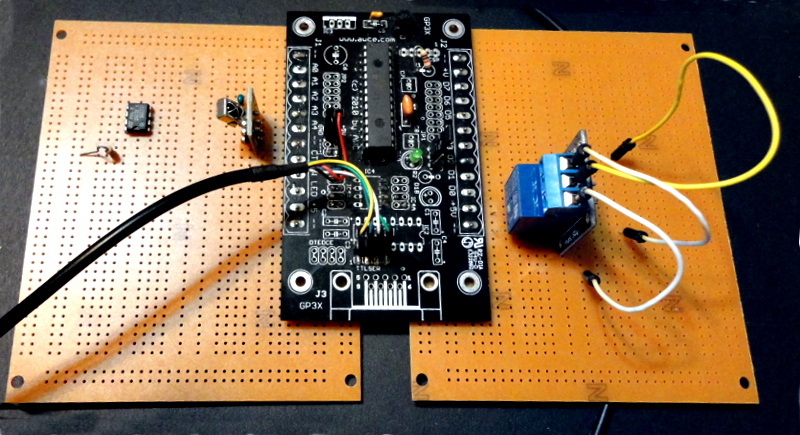
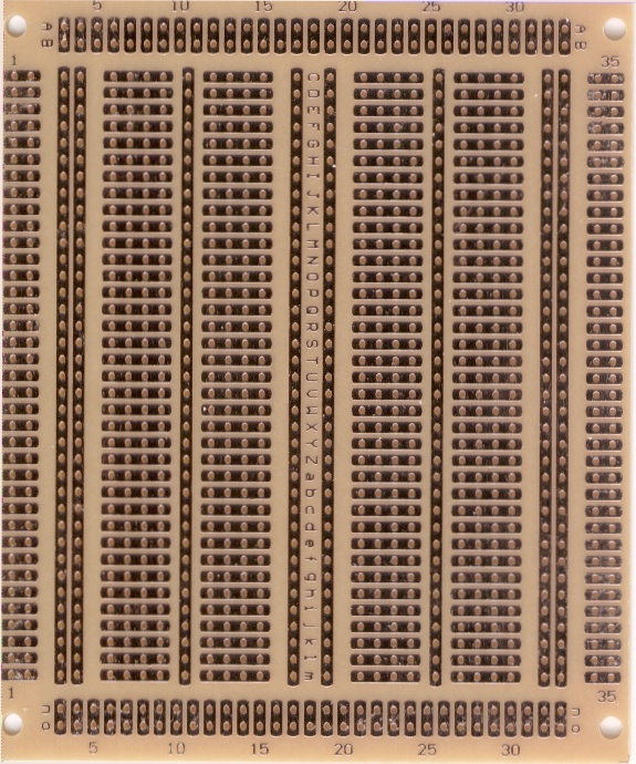
All the GP3 boards have pins on either .2" (GP-3X) or .1" (all others) spacing. You can easily connect these to prototype boards to get more space. We especially recommend using our PROTO1 board as "wings" (see photo above that shows two wings installed). You can add one to either side of the board or add two to maximize the space for custom circuitry. The hole pattern is handy (see photo) and will allow you to add ICs, relays, sensors, or anything else you need to use your GP3. If you plan to use wings, you'll probably want to order the board without screw terminals unless you intend to mount the screw terminals on the wings.
How do I get one?
Add to Cart GP-3/A complete kit (including screw terminals) $29.95SALE: $19.95
Add to Cart GP-3/A assembled (including screw terminals) $42.50
Add to Cart NEW! Prototype "wing" for additional prototyping space $4.99
Site contents © 1997-2018 by AWC, Houston TX (281) 334-4341